How to Use Your National Cash Register Class 400
Follow Directions
It is important to follow direction for the use of this register. Often a register is thought to need some repairs or adjustment when the trouble could be remedied by the following directions.
Some of the devices described herein are not used in all registers. These directions cover all devices applied to the various registers of Class 500.
The National Cash Register Company.
CONTENTS
|
Locks Nos. 1, 2, 3 and 5 |
3 |
|
Lock No. 6 |
4 |
|
To Operate Register |
4 |
|
Clerk's Initial and Special Keys |
4 |
|
Credit System Keys |
4 |
|
To Find Bow Much Money Should Be in Cash Drawer |
5 |
|
To Reset the Register to Zero |
5 |
|
Release Lever |
5 |
|
Detail Strip |
5 |
|
Customer Counter |
6 |
|
To Operate with Initial and Special Keys |
6 |
|
Back Of Check Printing Device |
6 |
|
To Put on New Roll of Check Paper |
7 |
|
To Ink Felt Roll |
7 |
|
Important |
7 |
|
If Check is not Issued |
7 |
|
To Put on a new Roll of Detail Paper |
8 |
|
To ReInk the Felt Inking Rolls |
9 |
|
To Put in New Ink Pad |
9 |
|
Numbering Device |
10 |
|
To Set the Constrain Numbering Wheels to Zero |
10 |
|
To Change Date |
11 |
|
The Turn-to-Zero Counter |
12 |
|
To Put on Front Electros |
12 |
|
How to Oil the Register |
13 |
|
To Clean Register |
13 |
|
How to Balance Register and Start Next Day |
14 |
|
Electric Attachment |
14 |
|
To Connect with Current |
15 |
|
To Make Registration |
15 |
|
To Put in Fuse |
16 |
|
To Put on New Roll of Paper |
17 |
|
Care of Motor |
17 |
|
Illuminated Indication |
17 |
|
General Remarks |
18 |
|
Price List of Supplies |
18 |
DIRECTIONS FOR USE AND CARE OF CLASS FOUR HUNDRED NATIONAL CASH REGISTERS
When register is taken from packing case place it on a solid level counter. Unlock register with keys tied to front which are numbered 1, 2, 3, 5 and 6.
Lock No. 1
On right‑hand side of register near top. Unlock this lock then adding wheels and the opening for resetting can be seen.
Lock No. 2
On right‑hand side of register, just to rear of and slightly below Lock No. 1. On electrically operated registers to the left of the release key. This locks keys and handle of register. The register cannot be operated until this lock is unlocked.
Lock No. 3
On back of register, near the center, this lock when unlocked prevents the register being used when the cash drawer is open. To lock, insert key and turn half a turn to left.
This lock not placed on registers built with multiple drawers.
Lock No. 5
This lock holds hoods in position over the printing device and electric motor. To remove hoods turn key to left, poll the knob of the catch down and release other catch at lower front of hood.
Page 3
Lock No. 6
This lock is attached to lids on front of register covering special and customer counters.
To Operate Register
Press keys showing the amount of sale, a special key showing the kind of sale and an initial key showing who made the sale. Press the handle slightly from you, then pull toward you and turn until it comes to a full stop.
A printed check will be issued, bell will ring, cash drawer will open, the indicators will show the amount, which will be added on the counter wheels and printed on the detail strip. Do not leave the checks in the receiver, as they will clog the printing mechanism.
Clerk's Initial and Special Keys
No register with clerk’s initial and special keys will operate before initial key is pressed; then sale can be registered, cash drawer will open and printed record of amount and special keys will be shown.
Credit System Keys
On credit system registers the "Charge," "Received‑on-Account” and "Paid‑Out" keys operate a special, counter which adds "1" each time a key is pressed and handle turned. These counters may be set to zero by turning from you small wheel at right until the counters show 000.
Page 4
To Find How Much Money Should Be in Cash Drawer
Unlock Lock No. 1 on right side, write down amount shown on adding wheels, subtract amounts shown by "Paid‑Out" slips; this sum added to the change should equal amount in cash drawer.
To Reset the Register to Zero
Unlock Lock No. 1, put resetting key in hole above handle on right side, turn from you as far as it will go. All adding wheels should then show zero. If any figure "1's" can be seen, reset counter. Take out resetting key by turning slightly backward and pulling to the right. Never attempt to start the handle until resetting key has been removed.
Release Lever
Located at the bottom and immediately to the right of the first row of keys is for the purpose of releasing any keys which may have been pressed by mistake. To operate this lever press down until keys release.
Detail Strip
To remove detail strip record unlock Lock No. 5, take off hood, pull strip forward a little and tear it off. (See cut in front of book.) Take out steel staple in spool "K," remove printed strip, then place blank end of strip on spool "K" and replace staple.
Page 5
Customer Counter
Between second and third row of keys, covered by lid, locked by Lock No. 6. This counter adds "1" each time register is operated, from 1 to 9999, then resets itself to zero. To reset by hand, turn from you the wheel on left until counters show 0000.
To Operate with Initial and Special Keys
The following does not apply to slip printing registers.
If a special key and a clerk's initial key are to be used in the same transaction, the special key must always be pressed before the initial key. If clerk "B" makes a Charge sale of $5, first press the "$5" key, then the "Charge" key, then his initial key and turn the handle. "Charge B $5.00" will be indicated and "Ch B $5.00" will be printed on check and detail strip. In this way two keys of different classes in the left row can be used together.
Back of Check Printing Device
The cylinder in the lower end of the check printer frame and the electrotype attached can be taken out by pushing up the latch marked "X" (see illustration) and pulling out the cap or covering. (Remove electro with small screwdriver.)
To put in cylinder, hold with type face upward, slide on shaft and move it forward and backward until the pin on the end goes into place, then put on cap and push down catch.
Page 6
To Put on New Roll of Check Paper
Door of hood may be opened or hood removed entirely. See that no pieces of paper are in printing mechanism. Have knob "G" at the word "On." Put roll of paper on stud, unwinding from bottom toward back of register. Cut paper off squarely, drawing through fingers to take out curve. Feed paper into opening below lower inking roll until it stops, then turn operating handle.
To Ink Felt Roll
Stir the ink well before using.
To ink felt roll in front of cylinder when checks become dim, use brush and ink sent with register. Put on just enough ink to moisten the roll.
If ink roll is taken out, put it back with the longer hub of the roller toward the register. If the felt wears out in after years, remove shaft by lifting and pulling it, out; take off flange at end of cylinder and pull off old felt. New‑felt must be soaked in ink furnished by the Company.
Important
When the check paper is nearly exhausted a check is issued with the words "Change Paper” printed upon it. This calls the attention of the operator to the fact that a new roll must be put on at once.
If Check is not Issued
If the register does not issue a check when the thumb‑nut "G" (see cut in front of book) is turned to the word "On," pull check paper entirely out of register, taking hold of paper where it enters "C." Take out scraps of paper in the printing mechanism with the tweezers.
Check‑printing registers should not be operated without the detail strip. If it is necessary to operate the register without check paper, turn the thumbnut "G" to the word "OFF."
To Put on New Roll of Detail Paper
The following does not apply to stub printing registers.
Remove hood over printing device. The detail record roll is the smaller one. Turn thumb‑nut ''G" (see cut) to word "Off" by pulling‑ out slightly and turning backward. Press an initial key, turn handle part way around, turn roll receiving paper forward until all figures on detail strip are rolled on receiving roll, tear the paper, take out steel staple, remove printed strip. Take off old core. Do not let paper unwind. Draw end of paper through thumb and forefinger to take out curve; place new roll on spool "J," press back as far as it will go. Paper must unwind from bottom of roll. Pass end of paper up through slot in “F," draw forward over rubber roll and over face of plate "F" and down over end of plate "F." Fasten end of paper to spool "K" with the steel staple. Put long end of staple in groove of spool "K." Turn spool "K" one or two times around. Complete revolution of handle. Turn thumb‑nut "G" to the word "On" and register is ready for operation.
Page 8
To Re‑Ink the Felt Inking Rolls
Stir the ink well before using.
When the impression on the check becomes dim, remove the hood covering the printing device. The two inking rolls, one in the rear and the other in front of printer frame where the paper enters "C", (see cut). These rolls should be inked with ink provided for this purpose. Put on only a small quantity of ink‑just enough to moisten the roll
By turning these rolls all parts can be easily inked.
Do not use any ink except that which is sent with the register, because it will dry or gum and prove unsatisfactory.
These rolls can be removed, if necessary, by taking out the shaft which supports them.
In replacing the rear ink roll the end with the two screws must be placed toward the register. The front ink roll must be replaced with the end with the two screws from the register.
Should it ever become necessary to change the felt on these rolls, remove the shaft by slightly lifting it tip and pulling it out, take out the two screws which hold the flange on the end of the roll, remove the flange and the old felt can be slipped off. Before the new felt is put on it should be thoroughly soaked with the ink.
To Put in New Ink Pad
Raise frame "A," pull pad out, moisten new pad with ink and slide same into the groove of frame "A" so that tongue of pad will fit in the small hole on top of frame.
Page 9
Numbering Device
Numbers from 1 to 9999, then automatically resets to zero. One is added each time a check is issued. If 25 checks are issued they will be numbered from 1 to 25, and the next one ready to issue will be numbered 26.
To register without issuing check, turn thumb‑nut "G" to word "Off."
When special keys are pressed checks are issued regardless of position of "On" and "Off" knob.
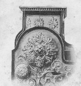
To Set the Consecutive Numbering Wheels to Zero
Remove hood over printing device. A small thumb‑nut will be seen just above the thumb‑nuts which change the date wheels. Turn this small thumb‑nut until the "0" stamped on it is directly under the "0" stamped on the check printer frame above it. Pull this small thumb‑nut out a trifle and turn in the direction of the arrow (stamped on it). The consecutive numbering wheels will then be set to print "000."
The first check issued will show a consecutive number as before, the second will have "000" printed on it. All following will be numbered from 1 to 9999, unless the wheels are reset to zero.
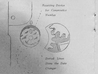
Text in photo reads: Resetting Device for Consecutive Numbers
Dotted Lines Show Date Changer
Page 10
To Change Date
Remove hood over printing device. The smallest thumb‑nut controls the months of the year and is numbered from I to 12; the second fixes the 10th, 20th and 30th days and is stamped 1, 2, 3; the third controls the daily wheels and is stamped from 0 to 9. On the cylinder is a small black mark which shows the proper line of the type on the dating wheels. The figures on the thumb‑nut should be in line with this mark.
These wheels change the day of the month
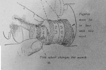
Text in photo reads: Figures must be in line with this mark
This wheel changes the month
To set the date to January 25, turn the smallest thumb‑nut from you until the figure "1" is opposite the black mark on the cylinder; turn second thumbnut until figure "2" is in line with figure "1"; turn third thumb‑nut until figure "5" is in line with figures "1" and "2." The second check issued will show this date.
The third thumb‑nut or daily date wheel should be changed each day; the middle wheel every ten days and the small wheel every month.
The first nine days of each month the second thumb‑nut is to be set to the blank space between "3" and "1," on the tenth day, the middle thumb‑nut is set to "1" and the third one to "0."
The Turn‑to‑Zero Counter
In upper part of right side of cabinet above Locks Nos. 1 and 2. Counts consecutively from 1 to 9999, resets to zero and begins again at 1. It adds one each time the dollars and cents counter is set to zero.
The proprietor taking a statement from the register makes note of the number shown by this counter and turns the dollars and cents counter to zero.
In taking the next day's statement this counter should show the next consecutive number.
Page 12
To Put on Front Electros
The electro is the type plate on printing cylinder attached with screws.
To put front electro on cylinder, turn handle halfway around; thick end must be placed down next to dating wheels and beveled edge tip.
If any part of background of electro marks the check, carefully locate the place and lightly pound it down with a blunt instrument. Always remember that the check printer cannot work well unless properly cared for and the type should be cleaned with benzene. A small screwdriver is provided in supply box to attach electro.
How to Oil the Register
Oil the check ejector, the printing table slide and the cam which operates the printing table about every two weeks. Oil can be had at any office or at the factory of The National Cash Register Company, Dayton, Ohio.
To Clean Register
Clean nickel‑plated case with warm water and soap, drying with chamois skin.
Never clean brass or bronze finished cases with anything but warm water, rubbing dry with a soft cloth. Most cleaning preparations contain alcohol or ammonia which cannot be used without damaging the case.
How to Balance Register and Start Next Day
1. Unlock Lock No. 5, press down the catch and take off hood.
2. Reset consecutive numbering device.
3. Change date.
4. Press an initial key and turn the handle.
5. Take off the printed detail strip.
6. Adjust detail strip.
7. Put on hood and lock Lock No. 5.
8. Unlock Lock No. 1 and take statement from adding wheels.
9. Reset adding wheels to zero.
10. Make a record of number shown by turn‑to‑zero counter.
11. Lock Lock No. 1.
12. Unlock Locks No. 6 and take statement from special counters.
13. Reset special counters to zero and lock Locks No. 6.
14. Balance cash.
Register is now ready for next day. The money can be taken out and the cash drawer left open at night, the clerk putting the change back in the morning, pressing his initial key and putting check number "000" in the cash drawer.
Keep register out of damp place and free from water.
Page 14
Electric Attachment
It is advisable to first operate the register by means of the handle before making the electric connection. This is to enable the user to become familiar with the various devices and operations as described in the direction book.
The handle can be easily attached or removed by pushing back the small catch, located near the point where the handle extends through the motor hood.
To Connect with Current
To connect the register with electric current, remove an incandescent lamp from its socket and screw in the current tap which is attached to the cord on the register. Turn the key in the socket ON. The register is now ready to operate by simply pressing an initial key.
To Make Registration
To make a registration, press keys representing the transaction you wish to register, then press an initial key. Always remove the finger from the keys, Should an initial key be held down during a registration, the key* must be released by means of the release lever before the register can again be operated.
Page 16
The register should be put in proper condition and operated by hand before turning the current on again.
It is advisable to remove the handle entirely when the motor is being used to operate the register, as there is danger of the handle being retarded in some manner, and in this way destroying the cartridge fuse. Should it be desired to operate the register with the handle, turn OFF the key in the lamp
To Put in Fuse
The fuse is located in the terminal block at the lower end of the motor.
Should the register be stopped in its operation by any accidental cause, the fuse will burn out unless the current is turned off at once.
When the fuse is burned out, the circle on the side will be blackened thus indicating that new fuse should be put in. In putting in a new fuse, care should be taken to place it in the holder with the circle showing, so if it burns out, it can be easily seen through the celluloid opening.
Page 16
The register should be put in proper condition and operated by hand before turning the current on again.
To Put on New Roll of Paper
When putting on new check or detail paper, the current should be turned off and the register operated with the handle.
Always remove the checks from the register as they are issued otherwise they may accumulate in the mechanism and prevent it from operating,
Care of Motor
A bottle of special oil accompanies the register for use in the motor bearings. These bearings are equipped with wick oilers and it is only necessary to refill the cups about every six months.
If the electrical connection is made without the use of the current tap, be sure to have the fuse which is furnished incorporated in the circuit; otherwise we will not be responsible for the successful operation of the register.
Under ordinary circum stances, the motor will require very little attention. Wiping the dirt and grease from the commutator and filling of the oil cups is all the care which should ordinarily receive. If anything unusual happens, or should you not understand these instructions notify the agent or the Company.
Illuminated Indication
On registers having this feature it is important that lamps of the proper voltage be used.
Page 17
Registers having four lamps are wired with the two lamps on each side in series, in which case the lamp voltage of each lamp should be one‑half the maximum line voltage.
Registers having but two lamps are wired with the lamps in parallel, in which case the lamp voltage of each lamp should equal the maximum line voltage.
Example: The motor plate calls for a line voltage from 110 to 120 volts. If a register with four lamps in series, a 60‑volt lamp should be used. If a register with two lamps in parallel a 120‑volt lamp should be used.
If there is but one voltage specified, consider it the minimum voltage and allow for an added variation of about ten volts.
Example: The motor plate calls for 110 volts, furnish a 60 or 120volt lamp which allows for the added variation.
General Remarks
Never keep keys of register in cash drawer,
Once a month drop a little oil on knives cutting off checks.
Clean numbering, dating wheels and type with small brush and benzine. Press top row of keys and turn handle to reach ‑all figures.
If you do not understand these directions clearly or if you have trouble with your register, do not tinker with it, but notify the agent.
Page 18
Price List of Supplies
Check paper can be obtained through our local offices or by writing to The National Cash Register Company, Dayton, Ohio. This paper is furnished in white, green, yellow or pink. An assortment of colors can be obtained in one shipment. Some merchants prefer using different colors on certain days of the week.
In ordering printed supplies, detail strip or check paper always send sample and order two weeks in advance of the time you will need it.
In ordering supplies amounting to less than, $2, remit payment in advance. This is requested in order to avoid the necessity of opening a large number of ledger accounts for small items. We receive thousands of small orders for supplies which, if charged on open account, would entail expenditures of a vast amount of time and labor.
Following are prices for supplies used with this register. These prices are F. 0. B., Dayton, Ohio, subject to change without notice effective in the United States only.
Our agents in different parts of the country are privileged to make an extra charge to cover the cost of transportation, and handling.
|
Check paper, X or XX per roll |
$0.06 |
|
Check paper, X or XX in lots of 100 to 300 rolls, per roll |
.05 |
|
Check Paper. X or XX in lots of 300 rolls or more to |
.04 1/2 |
|
Check paper. XXX, per roll |
.07 |
|
Check paper, XXX in lots of 100 to 300 rolls, per roll |
.06 1/2 |
|
Check Paper. X or XX in lots of 300 rolls or more to |
.05 3/4 |
|
Detail paper rolls size C, 10 rolls |
.20 |
|
Detail paper rolls size F, 10 rolls |
.25 |
|
Detail paper rolls size H, 10 rolls |
.35 |
|
Ink, per can |
.10 |
|
Electros to print back of check |
.60 |
|
Electros (small size) either upper or lower, to print front of check |
.40 |
|
Felt pads for printing segment, per dozen |
.25 |
|
Printed sales books, less than 500 books |
.04 |
|
In lots of 500 to 1000, each |
.03 ½ |
|
In lots of 1000 or more, each |
.03 |
|
Covers for sales books, each |
.15 |
|
Extra carbon sheets for order books, per dozen |
.10 |
|
“Paid‑Out” pads (100 sheets each), per 10 pads |
.15 |
|
Clerks' daily statement pads, per 10 pads |
.20 |
|
Purses, large, each |
.20 |
|
Purses, small, each |
.15 |
|
Statement books, Form 10 or 11 |
1.00 |
|
Statement book for multiple‑drawer register, Form 14 |
1.00 |
|
Oil (2‑ounce bottle) |
.10 |
|
Oil can (filled) |
.15 |
|
Vest pocket memorandum books, each |
.15 |
|
Pin files, each |
.10 |
|
Fuses for electric registers, four for |
.50 |
Certain supplies can be sent by mail or express prepaid at less expense than if they were forwarded by express collect. Therefore customers will find it to their advantage to send with orders for such supplies a sufficient additional remittance to cover transportation charges. Below is a schedule of various articles on the transportation charges of a saving can be made if prepaid, and the amount required:
Ink, can ‑‑‑‑‑‑‑‑‑‑‑‑‑‑‑‑‑‑‑‑‑‑‑‑‑‑‑‑‑‑‑‑‑‑‑ Postage $0.05
"Paid‑Out" pads:
10 pads ‑‑‑‑‑‑‑‑‑‑‑‑‑‑‑‑‑‑‑‑ Expressage .15
20 pads ‑‑‑‑‑‑‑‑‑‑‑‑‑‑‑‑‑‑‑‑ Expressage .20
30 pads ‑‑‑‑‑‑‑‑‑‑‑‑‑‑‑‑‑‑‑‑ Expressage .26
40 pads ‑‑‑‑‑‑‑‑‑‑‑‑‑‑‑‑‑‑‑‑ Expressage .35
Clerks' daily statement pads (for multiple‑drawer registers)
10 pads ‑‑‑‑‑‑‑‑‑‑‑‑‑‑‑‑‑‑‑‑ Expressage .20,
20 pads ‑‑‑‑‑‑‑‑‑‑‑‑‑‑‑‑‑‑‑‑ Expressage .40,
The National Cash Register Co. Dayton, Ohio.
Form 11‑11‑9‑09‑5m‑1104‑165
These Cuts Apply to the Slip Printer Register Only
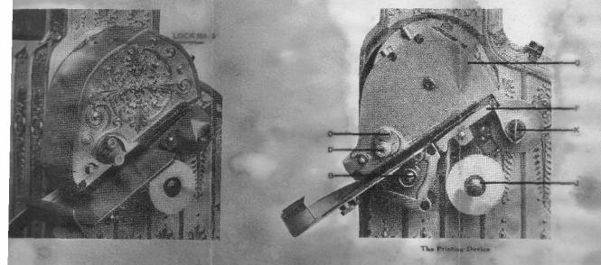
ed-- The Photo above shows Lock No. 5 The 2nd photo shows on the left items O, D and G and Q, F, K and J on the right.
This cut shows a section of the right-hand side of the register and Locks No. 1 and No. 2. When the slots in the center of the locks are in the positions indicated above, the locks are locked; when they are turned forward hey are unlocked.
This cut shows a section of the hood which covers the printing device and tilt position of Lock No. 5.
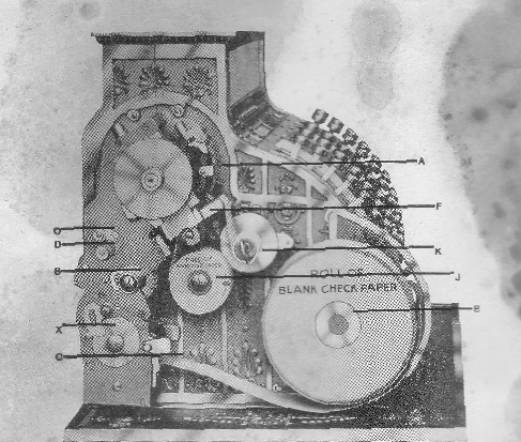
The Printing Device Check and Sales Strip Printer.
Ed- The photo above shows items O D G X and C on the left and A, F, K, J, and B on the right.
GUARANTEE
Following is a copy of the guarantee, which is on bottom of the cash drawer. It bears the factory number of register and date and name of purchaser.
We hereby warrant this register to be mechanically correct. Should the register get out of order from ordinary use any time within two years of the, above date, we agree to repair it free of charge, provided:
1. That no alterations or additions have been made to the machine except by us or our authorized representative.
2. That you send it to our factory or to our nearest agency having a repairman, transportation charges both ways on the register to be paid by you. However, should you desire the services of our mechanic at your place of business instead of sending the resister to our agency or factory, you are to pay the cost of said mechanic's journey to and from your place of business.
The National Cash Register Co., Dayton, Ohio.
President
John H. Patterson